
Introduction
An ER Diagram is a pictorial representation of entities and relationship described by the data. ER Diagram helps to understand the logical structure of the database.
ER Diagram is also known as ER model. ER model is a high level conceptual data model diagram. It helps to generate the well-designed database system by analysing the requirements. ER diagrams are like flowchart that describes the flow of the system in a systematic way. ER diagram is widely used in database design. Some tools for designing ER diagram are creately, smart draw, lucid chart, diagrams.net, etc. There are many tools that can be found on internet.
The components of ER model are:
Entity
An entity is anything in real world system that can be uniquely identified. An entity can be person, place, objects, events, etc. Entity are the tables. A weak entity depends upon the existence of another entity. A weak entity cannot describe itself, it must use its foreign key to provide appropriate result.
Attributes
The descriptive property of an entity is called attributes. For example, there is every student, who can be recognized by their registration number. An entity can have many attributes including the key attributes. An entity cannot be empty.
Relationship
A relationship is the association between entities. A relationship describes how the entities are related to each other. For example, a library can have many books, a teacher teaches many students, etc. The objective of a ER diagram is to model relationship among entities. The relationship that can be formed are:
- One to one (eg. A rider rides cycle)
- One to many (eg. A teacher teaches many students at a time)
- Many to many (rg. Many readers read many books)
The symbols used in ER Diagram are:

Rectangle – It is used for representing an entity.

Oval – It represents an attributes

Oval with underlne – It represents a key attribute.

Diamond – It represents relationship

Undirectional line – It represents relationship many.

Directed line – It represents relationship one.
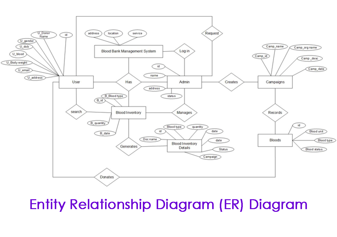
ER Diagram

Why use ER model?
- It is used for designing relational databases.
- It is mostly used in software engineering field during project planning.
- ER Model is useful in analysing the existing database to find and resolve problems.
- ER Model helps in understanding the flow of how the system works.
- It helps to describe entities, attributes, and relationship.
- It allows you to communicate with the logical structure of the database to users
I was recommended this website by my cousin I am not sure whether this post is written by him as nobody else know such detailed about my trouble You are amazing Thanks