

Introduction
The physical layer of the OSI model is the cornerstone of data communication. It handles the raw transmission of data bits through various media, ensuring that the foundation for all network activities is stable and reliable.
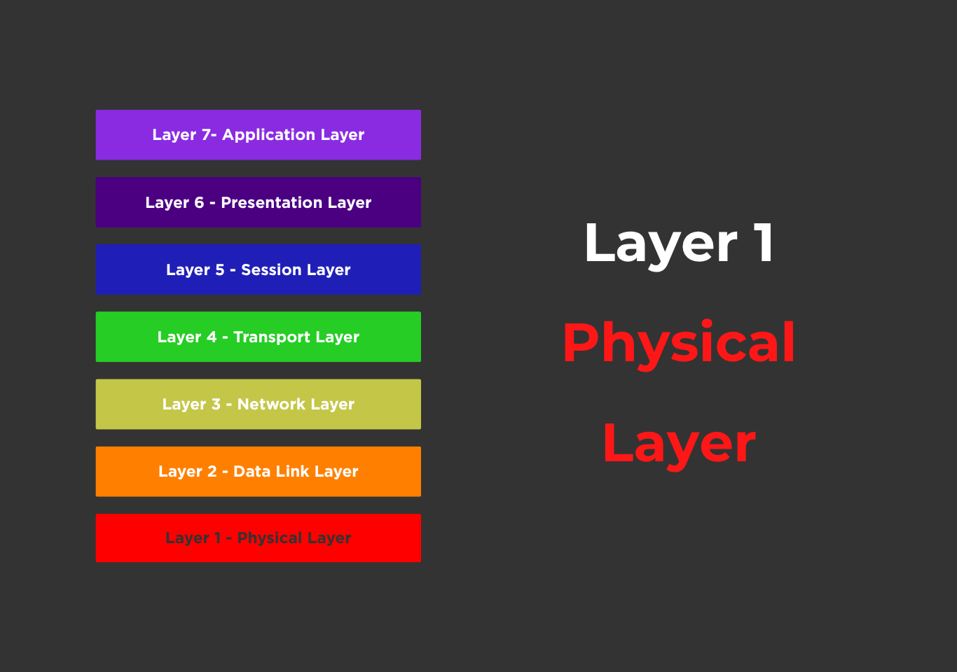
The physical layer is the OSI (Open Systems Interconnection) reference model’s lowest layer (Layer 1) and is in charge of transmitting raw data bits over a physical media such as copper wire, fiber optics, or wireless radio waves. Unlike the higher levels, it does not evaluate data meaning and instead concentrates solely on how bits are transferred and received electrically, optically, or electromagnetically. It is concerned with sending raw bits (0s and 1s) over a physical data link between network nodes. The physical layer defines the network’s hardware parts, which include cables, switches, and routers. It also describes the electrical, mechanical, and procedural aspects required to activate, maintain, and deactivate physical connections.

This layer specifies the mechanical, electrical, and procedural interactions with the physical transmission medium. It covers cables, switches, voltages, pin layouts, data rates, signal modulation, and the physical connection of network devices. For example, the physical layer defines and manages Ethernet cables (e.g., Cat6), fiber-optic cables, and wireless RF signals. The physical layer collaborates with the data link layer, which organizes these bits into frames. It has a significant impact on the speed and dependability of a network connection. The physical layer is the foundation of all communication systems, connecting hardware to the abstract realm of data exchange.
The main functions of the physical layer include the following:
- Bit-by-bit data transmission over the medium.
- Encoding and modulation of data into signals.
- Synchronization of bits between sender and receiver.
- Determining signal strength, wavelength, and attenuation.
- Handling physical topologies such as star, bus, or ring layouts.
- Line configuration, such as point-to-point, multipoint
- Physical medium specifications like cable types (coaxial, twisted pair, fiber), connector(RJ45, SC, LC), length limitations
Features of the physical layer
The following are the main characteristics that define the physical layer:
- Hardware-centric: focuses on cables, connectors, voltage levels, and signal frequencies.
- Bit-level transmission refers to the transmission of raw bits.
- Behavior varies according to media (copper, fiber, or wireless).
- Lacks data interpretation: It does not recognize data structures such as frames or packets.
- The physical layer is protocol-agnostic, meaning it operates independently of higher-level protocols.
Devices Operating at the Physical Layer
Several hardware components operate at the physical layer, including:
- Cables (e.g., Cat5e, Cat6, coaxial, fiber optic)
- Hubs
- Repeaters
- Network Interface Cards (NICs)
- Modems
- Media Converters
Transmission media types
Guided transmission media, also known as wired or bounded media, are physical routes that carry signals from one device to another. Twisted pair cables, coaxial cables, and fiber-optic cables are all common forms.
- Twisted pair cables are commonly used in telephone networks and local area networks (LANs). They are made up of twisted wire pairs that are designed to reduce electromagnetic interference.
- Coaxial cables feature a center conductor, insulation, shielding, and an outer jacket, making them appropriate for cable TV and the internet.
- Fiber-optic cables send data by light pulses through thin glass or plastic fibers, providing high bandwidth, long-distance transmission, and resistance to electromagnetic interference.
When compared to wireless alternatives, guided media provides higher levels of security, reliability, and data transmission speed. However, installation can be expensive and complicated, particularly across large distances. Despite this, guided media is preferred in places that demand consistent and fast connections, such as data centers, corporations, and universities.
,
Unguided transmission media, often known as wireless or unbounded media, are communication channels that send signals across the air or space without utilizing physical conductors. This comprises radio, microwave, and infrared communications.
- Radio waves are extensively utilized for broadcasting, Wi-Fi, and Bluetooth. They can travel long distances and penetrate walls, making them suitable for large-scale communication. Microwaves are employed in satellite communication and point-to-point communications to provide higher frequencies and directional signal pathways. Infrared is commonly utilized for short-range communication, such as in remote controls and wireless sensors.
- Wireless media provides flexibility, portability, and scalability, which is especially beneficial for smartphones, laptops, and IoT devices. It also lowers infrastructure expenses because no wires are required. However, wireless communication is more vulnerable to interference, security threats, and signal deterioration as a result of barriers or weather.
Unguided media is critical in enabling wireless networks, remote access, and mobile technologies. As the demand for mobile data and internet access increases, wireless transmission becomes more crucial in both urban and rural areas.
Standards and Protocols at the Physical Layer
- IEEE standards
- IEEE 802.3 (Ethernet): Defines physical and data link layer standards for wired LANs.
- Includes 10BASE-T, 100BASE-TX, 1000BASE-T (Gigabit Ethernet), etc.
- IEEE 802.11: Physical layer specs for Wi-Fi (wireless LANs).
- Includes 802.11a/b/g/n/ac/ax.
- ITU-T Standards
- V-series (e.g., V.92): Defines modem communication over telephone lines.
- G-series (e.g., G.703): Defines transmission over digital networks like ISDN.
- ANSI/TIA/EIA Standards
- TIA/EIA-568: Cabling standards for structured telecommunications wiring (e.g., Cat5e, Cat6 cables).
- Defines pinout, wire color codes, and connector types (RJ-45).
- ISO/IEC Standards
- Defines generic cabling systems and supports various media types and network topologies.
- USB (Universal Serial Bus)
- Defines connectors, signaling, and protocols for data transmission between computers and peripheral devices.
- NRZ (Non-Return to Zero), Manchester, 4B/5B
- Encoding schemes that define how bits are converted to electrical signals.
- DSL (Digital Subscriber Line)
- Protocol used for high-speed internet over telephone lines.
- DOCSIS (Data Over Cable Service Interface Specification)
- Protocol standard for transmitting data over cable TV systems.
Types of errors at the physical layer
These errors typically affect the electrical, optical, or radio signals that represent data:
| Errors | Description |
|---|---|
| Bit errors | A 0 is mistakenly received as 1, or vice versa. |
| Signal distortion | Signal changes shape due to medium or hardware imperfections. |
| Attenuation | Signal weakens over distance. |
| Noise | Random electrical interference distorts signals. |
| Crosstalk | Signal interference from nearby wires or channels. |
| Jitter | Irregular signal timing causes synchronization issues. |
Error Handling Mechanisms
- Signal Encoding and Modulation.
Manchester encoding, 4B/5B, or NRZ are used to improve the reliability and detectability of signal transitions. Helps synchronize the sender and receiver. - Physical Layer Standards.
Miscommunication is reduced by using defined voltage ranges, timing, impedance, and connectors. For example, Ethernet (IEEE 802.3) defines precise timing and voltage to reduce errors. - Repeaters and amplifiers.
Repeaters clean and regenerate signals across long distances, preventing attenuation. Amplifiers boost weak signals (although they can also magnify noise). - Shielding & Twisting
Cables such as twisted pair and coaxial lessen electromagnetic interference. Fiber optic cables are not susceptible to electromagnetic interference (EMI). - Parity Bits and Line Coding (rare at Layer 1).
Some encoding systems may incorporate redundant bits to ensure signal integrity. Error detection is mostly handled by the Data Link Layer, while certain legacy devices (such as modems) used parity at Layer 1.
Physical Topologies in the Physical Layer
Bus topology
Bus topology connects all devices to a single central wire known as the backbone. Data travels in both directions, and each device listens for its address before accepting data. It is simple and inexpensive, but it is prone to collisions, has a short wire length, and is difficult to troubleshoot. A failure in the main cable takes down the entire network. It is mainly obsolete today, superseded by more dependable topologies; however, it was ubiquitous in early LANs that used coaxial cables.
Star topology
A star topology connects all devices to a centralized hub or switch. Data from one device travels through the hub to reach the others. It is the most widely used topology today due to its dependability, ease of troubleshooting, and scalability. If one cable or device breaks, the rest of the network remains operational. However, if the central hub fails, the entire network goes offline. It takes more wire but provides excellent performance and is widely utilized in Ethernet-based LANs.
Ring topology
Ring topology connects each device to two others, resulting in a closed loop. Data can move in one way (unidirectional) or both (bidirectional in dual-ring configurations). Each gadget functions as a repeater, amplifying the signal as it travels. It reduces collisions but is very dependent on each node; a single failure can disrupt the entire network. It was utilized in older systems such as Token Ring, but is now rarely used due to maintenance issues.
Mesh topology
Mesh topology connects all devices directly. It has great fault tolerance and redundancy, so even if one link fails, data can be rerouted through another. There are two types of meshes: full mesh (every device is connected to all others) and partial mesh. It has good performance and dependability, but it is expensive and difficult to install due to considerable cabling. It is utilized in backbone networks, military systems, and high-availability settings.
Hybrid topology
A hybrid topology combines two or more topologies (e.g., star-bus, star-ring) to meet specific network needs. It benefits from the strengths of each type and minimizes their weaknesses. For example, a star-bus topology uses star-connected devices linked via a bus. It’s scalable, flexible, and widely used in large organizations. However, complexity increases with size, and maintenance can be more demanding. Hybrid topology is highly adaptable to modern networking environments.
Advantages and Disadvantages
Advantages
- Standardization ensures device interoperability.
- Supports high-speed data transmission.
- Flexible choice of transmission media.
- Provides a reliable electrical or optical signal foundation.
- Essential for upper-layer operations.
Disadvantages
- No built-in error detection or correction.
- Vulnerable to physical interference and noise.
- Security risks through physical access.
- High installation and maintenance costs.
- No understanding of data structure or meaning.